

 Tweet
599
Originally posted by T-rex
View Post
Notes on the Crystal Set
When measuring the velocity difference between underground and our ground, the two seperate receivers can be brought into phase unison by the use of a test oscillator. Both receivers must have a primary tank circuit, here you can place your measurement equipment.
The detected AM output, audio frequency, signal is immune to receiver phase shift. This is a property of A.M. detection. Use the audio to measure propagation delay.
Wind all coils in the same direction, this is a must! Brass is a very good primary material, good depth of penetration at broadcast frequencies. Wires and clip lead interconnection are the "Road to Absolute Defeat." Coils and Condensers must be merged into each other in broad surfaces. Stacked metal plates on insulators makes good condensers. Transmitter air condensers are good, vacuum condensers are the best. A number of small condensers are better than one big one, less stray inductance. Stray inductance is fatal to success! For smaller units silver mica condensers are the only way, use no others. Paralell them on a low inductance bus.
Do not get sidetracked, experimental and auxilliary coils as well as patent diagrams will get you stuck in the sand forever. The finished Colorado unit dimensions are all in the notebook. It is all there, look at it, not the diversions, and remember everything you thought was Tesla is the exact opposite. It is there; one or two turn primary; a 20% height/width secondary; and a 100% height/width extra coil, all there, wire size, turns, all there, can you find it? It then can be scaled to any frequency and any KVAR capacity within wavelength conditions.
As your unit gets perfected the signal gets stronger and stronger, then diodes start burning out. We then are reaching the engineering objective, that is to light a number 327 pilot lamp. Not much power but too bright for Einstein.

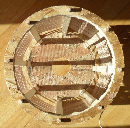
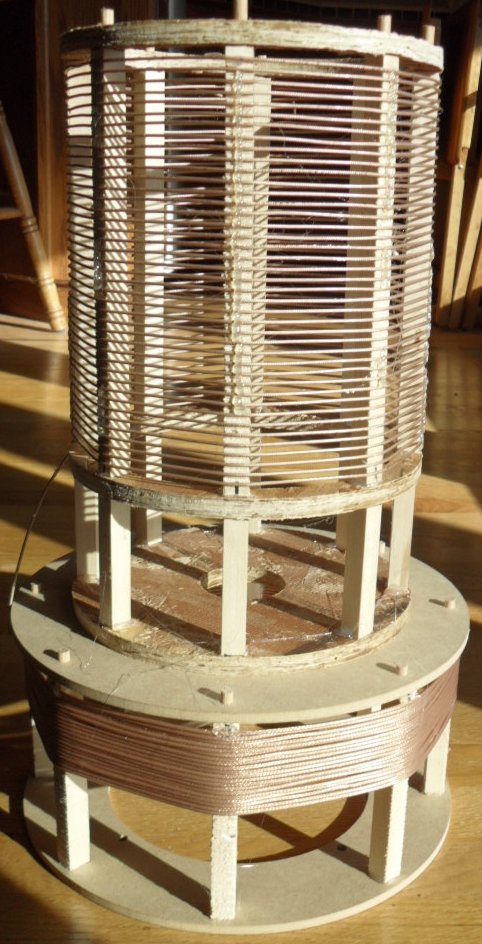


 It's been a while since I've done my college math courses, so if I'm missing something, please point it out.

Comment