

 Tweet
Originally posted by Sputins
View Post
-
Thank you for sharing that great info and the PDF, THANK YOU!"Rebellion to tyrants is obedience to God." - Benjamin Franklin + Thomas Jefferson

-
Bad ass man!Originally posted by evostars View Post
I blew out a single LED the other day and it was quite rewarding. I also blew out some opto couplers, that was less rewarding, now I have to wait on more parts... "Rebellion to tyrants is obedience to God." - Benjamin Franklin + Thomas Jefferson
Comment
-
Damn!
I had no IDEA! Now I've got another set of things to mess with in regards to the bifilar, thank you!Originally posted by Allen Burgess View Post
We'll see if I can blow out some electrical equipment at a distance"Rebellion to tyrants is obedience to God." - Benjamin Franklin + Thomas Jefferson
Comment
-
I know this is nothing to laugh about b/c it's 100% serious, but LOL!Originally posted by Allen Burgess View Post "Rebellion to tyrants is obedience to God." - Benjamin Franklin + Thomas Jefferson
Comment
-
-
Turned out, both diodes were broken. only one blew up. Pretty strange. seems the charge in a capacitor can move around really quick.Originally posted by ET-Power View Post
I had the system running (caps charged) but had forgotten to attach the dc meter. hooked up to the positive first. noting happened. But then I hooked up the negative and BAM.
Luckily i bought more of them at the same time. So i didn't have to wait on the postman.Comment
-
-
Indeed the magnetic field should be confined like that. great suggestion. I would start with only a flat cylinder in the middle.Originally posted by Ufopolitics View Post
Yes visualisation is one of my plus points. The videos show the (DC) fields, but there is more to them. they also spiraling (you and I know how from ken wheeler and the ferrocell I guess).
About the dielectric field. it is indeed between the wires. But, thats in a DC current situation. with ac at its resonant frequency, things change.
Im still in the process of understanding what happens then (i want to make a video about it).
I seems the dielectric lines up with the magnetic field, and becomes one(magneto dielectric). The magnetic field is still there, but the dielectric field, is all around.
If I have a metal plate, completely removed from the system, and i put my oscilloscope probe on it, It reads the same sine wave signal. So it seems the field is expanded outwards. Even when I dont touch the wires with my probe, the signal is already there.
This is why I focus on the dynamic dielectric field.Comment
-
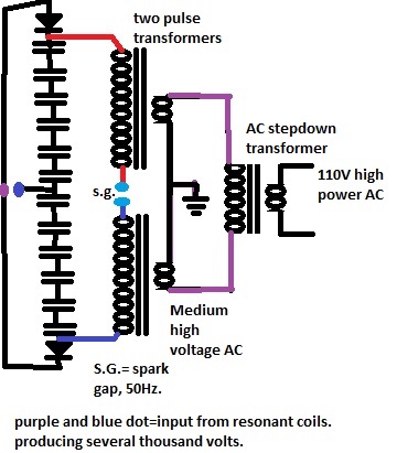
I thought about how to extract energy from a high voltage system. As that is a tricky thing. It all needs to be tuned. In the attached drawing I used 2 pulse transformer, to generate AC on the secondary.
Don't know if this would work, but it would be a way to transform the high voltage into low voltage, high current.
The spark gap, would also be part of the system, I believe it should be in the center of the bifilar coils, as that would return some of the spark energy back into the system.Attached FilesComment
-
-
Thanks for sharing!Originally posted by tysb3 View Post
I can't understand a word, but the pictures tells me we are on the same path.Comment
-
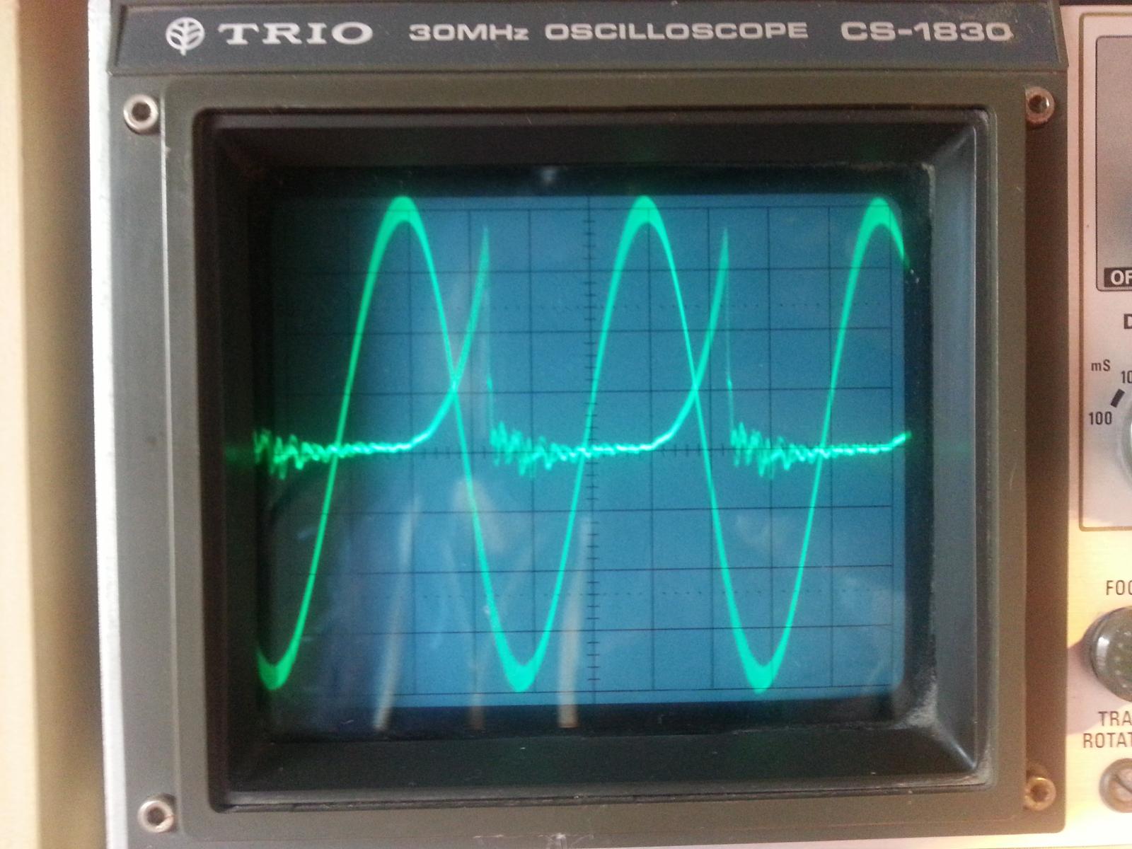
screenshot of the relation between the pulses of the center coil, and the resonant sine wave of the reversed south coil
edit: notice they are out of phaseAttached FilesLast edited by evostars; 04-15-2017, 08:36 PM.Comment
-
-
I really need a proper lesson in high voltage safety before i proceed.
Has anybody got a good link?
I just got shocked by my capacitors. I thought they where discharged.
after discharging the diode side, of my 4 series connected capacitors, there still was a charge left from the middle capacitors.
Doesnt make sense to me. but apperently you need to dicharge all capacitors separate, when they are in series?
Luckily I know the one hand rule. it discharged via one hand. So not through my whole body (heart). It gave me a good laugh, and a proper warning.
I really need a proper lesson in high voltage safety before i proceed.
Has anybody got a good link?Comment
-
I replaced my variable tuning capacitor with a 200pF capacitor. It only has a 100V rating, but its in the resonant frequency coil, where there a re standing waves. The voltage over the cap is around 450Vac at 482kHz and it seems to work just fine. Its for tuning the coilComment
-






Comment