This forum is preserved as a permanent archive. The community continues at eMedia Press.

Announcement

Collapse
No announcement yet.

The GEGENE : a Great Efficiency GENErator with a Tesla bifilar coil

Collapse
X
 
  • Filter
  • Time
  • Show
Clear All
new posts

  • @Paul

    review this for basic refreshing of simple filtering.

    http://www.navymars.org/national/tra...m=auto,-21,168


    Also I am still studying your diagram and it dawned on me that

    you have an excellent working extra energy producing device so

    we wouldn't want to change it completely. What you should do

    is to leave the system alone and use one of the filters to get a

    few hundred watt off to say your refrigerator. I do refrigerator work

    every day here and today my only fun was replacing the lower

    cooling fan to facilitate hot air movement.


    But a standard refrig. is a great starting point.

    Tap in to one of your lines that provides the correct voltage.

    Oh and yes I work on electric range, digital controls the whole

    smear. And you really goofed when you did not

    provide the correct freq and volts to that beauty you smoked.

    Oh well, live and learn right? Nothing ventured, nothing gained.

    It is very important for digital clocks designed for 60hz that they

    get EXACTLY what they are made for. If 60hz can be attained

    then also remember that 240vac must also to delivered.

    If 250volts is supplied to a digital stove the life will be greatly shorten.

    On the other hand I use a genset that runs my frig in storms

    and it is not so sensitive. For instance I normally run it all day on

    120vac(240euro) but sometimes my genset climbs up to 135vac(270euro) and as

    long as there are no computers in your frig you can get away

    with a few mistakes, however running the frig winding on the

    compressor at elevated voltages will stress the winding in the

    long run. If it survives the elevated voltages will be needed

    in the future to run it as break down has occurred.

    From what I can tell from the diagram you are running

    series parallel. I really have not figured out your diagram yet.

    It looks like 220 volt water heater in series with 220vac water

    heater. I will study it more till I see how it works.

    Look at my PDF. a few parts on the back of a frig could

    get it running, I just know it. Instead of trashing a frig

    find a small 1/2hp electric motor like in a washing machine

    and test with that. Or a 1/3hp dryer motor, a dryer will run

    3.5 amps(1.75 euro) without a belt on it same as a frig compressor

    winding. From there it is all down hill. All my stuff runs on 120vac.
    Last edited by BroMikey; 08-04-2015, 05:38 AM.

    Comment


    • Hey Paul

      A hot water heater is a great resistor AND it provides a useful

      task while it is resisting. The first question to ask is what is the

      VOLTS

      across one of your hot water heaters? I know it has to be close to

      220vac but it is important to know the actual voltages across one

      of those resistors. Do the voltages always stay the same ALL of the

      time? From there you got it whipped. If you have a stable voltage

      you have half the battle won.

      I remember one post you saying within 100 volt changes

      Humm.... So that would mean 480vac for two water heaters

      goes up and down that much?
      Last edited by BroMikey; 08-04-2015, 05:35 AM.

      Comment


      • Originally posted by BroMikey View Post
        Hey Paul

        A hot water heater is a great resistor AND it provides a useful

        task while it is resisting. The first question to ask is what is the

        VOLTS

        across one of your hot water heaters? I know it has to be close to

        220vac but it is important to know the actual voltages across one

        of those resistors. Do the voltages always stay the same ALL of the

        time? From there you got it whipped. If you have a stable voltage

        you have half the battle won.

        I remember one post you saying within 100 volt changes

        Humm.... So that would mean 480vac for two water heaters

        goes up and down that much?
        Thanks for the replies Mike and Randy

        I will measure the voltage across the heaters as soon as I am back home again,and yes we have 220Vac in my country at 50HZ. What I meant by the difference in Voltage Mike was that the first coil tested 980V and the second coil(lying on top of the first coil)had 880V,that was measured directly at the cooker not across the wires at the water heaters.My heaters thermostats are set at 50deg celcius and is warm enough for showers and baths,and what I actually should do as well is to measure the temperature with a thermometer and see what I get,if it is 50Deg then i am happy.
        And like I said earlier the Voltage varies depending on the wheater and the position of the sun,but it varies not more than 100-120volts,at one stage in the summer,just before sunset I measured 1200V<and that was measured with an simple multimeter(the only one I have)
        So yes,This is something new to me.

        Randy
        I don't quite understand what you want to tell me,I am new at this,could you please explain in a bit more detail and maybe a sketch?

        Thanks to you all

        Paul

        Comment


        • @quantumfanatic - that pdf you posted is imo a complete waste of time. First off, there's no proof that he actually built any of it - not one photo of a build! Second, you have to read half-way through the document before you come to the admission that he has never actually done a build that used SCR's - how much more damning do you need! Also note that never does he mention anything about output waveforms - his (mythical) output is a squarewave, just switched battery-voltage, not the lowest common denominator in the inverter scene that you can buy, a modified squarewave output, never mind a pure sinewave output, the most expensive type available. Note also that most inverter manufacturers advise not to use modified-sine inverters on televisions, computers etc. never mind squarewaves - yet he talks of doing just this in the document, with sage-advice like in his opinion, they wouldn't be damaged if/when the bolts he speaks of using fuse while in operation. Unbelievable.

          Also, is there one example on Youtube of anyone claiming a 5,000 watt inverter using relays/bolts/big nails??? Not to my knowledge, the reason being, it's totally impractical.

          Finally, your garden-variety meters, both voltage and clamp-meters, are specifically designed to measure ac voltages/currents in the 50/60Hz frequency-range, not in the 15-25Khz frequency range we are dealing with here. Your voltage variations are much more likely to be due to this than to the sun. You need at least a scope to know what your true output voltage is, particularly since the induction hob is ramping up & down the frequency as it adjusts it to the load it percieves - your pot.

          The only intersting home-build that I have come across is this - https://www.youtube.com/watch?v=nc-Mnmkax6g Definitely 'cheerful', but given the current price of 500W cores, maybe not so cheap.
          Last edited by sprocket; 08-04-2015, 03:23 PM. Reason: updated youtube link...

          Comment


          • 5000 watt inverter

            Hello Sprocket

            Thanks a lot for your honest opinion,like i said earlier,i know very little about electronics,but am willing to learn from however are willing to teach me,but thanks,the little i know ,or my intellect told me it's to good to be true,that's why I posted it,i wanted to learn from people who actually knows whats cookin,me haha,a dumn scheit.
            Do you have an idea how I can make the system more user friendly for electronic appliances,i.e to be able to use it with my fridges,microwave and TV set?I'm sure you read my earlier posts,that's why i'm asking(I am not into videos...to long and inconclusive...schematics are more than welcome)

            Regards

            Paul

            Comment


            • Sprocket

              At least I know also the difference between a square wave and true sine wave...but thanks again,thought it was scheit

              Comment


              • Originally posted by sprocket View Post
                @quantumfanatic - that pdf you posted is imo a complete waste of time. First off, there's no proof that he actually built any of it - not one photo of a build!


                Finally, your garden-variety meters, both voltage and clamp-meters, are specifically designed to measure ac voltages/currents in the 50/60Hz frequency-range, not in the 15-25Khz frequency range we are dealing with here.


                The PDF is not a comprehensive engineering design guide

                complete with all the details of 10,000 page "HANDBOOK"

                the PDF establishes certain basics for filtering frequencies.

                The meter reading is off so what about a suggestion to rectify

                the AC into DC? Any suggestion Sprocket? Or just rants?

                Remember Quantum doesn't understand the complexity

                of the scope shots or even have one. Will rectified DC

                make you and the meter happy?

                I guess the main thing here is the 2 heaters are doing the job.


                Nice inverter

                Originally posted by sprocket View Post
                The only intersting home-build that I have come across is this - https://www.youtube.com/watch?v=nc-Mnmkax6g Definitely 'cheerful', but given the current price of 500W cores, maybe not so cheap.
                Last edited by BroMikey; 08-04-2015, 05:55 PM.

                Comment


                • Originally posted by quantumfanatic View Post
                  Hello Sprocket

                  Thanks a lot for your honest opinion,like i said earlier,i know very little about electronics,but am willing to learn from however are willing to teach me,but thanks,the little i know ,or my intellect told me it's to good to be true,that's why I posted it,i wanted to learn from people who actually knows whats cookin,me haha,a dumn scheit.
                  Do you have an idea how I can make the system more user friendly for electronic appliances,i.e to be able to use it with my fridges,microwave and TV set?I'm sure you read my earlier posts,that's why i'm asking(I am not into videos...to long and inconclusive...schematics are more than welcome)

                  Regards

                  Paul
                  Hey Paul

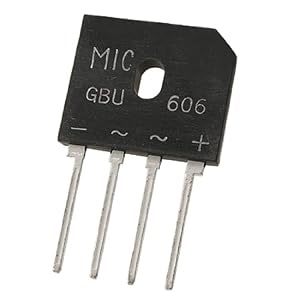
                  I guess SPROCKET is right about the meters. Look at this picture


                  This small bridge could give us a more accurate voltage reading.

                  Especially under loaded conditions we need a stable volt reading.

                  If you hook up a bridge the meter may reveal only 90volts or it may

                  reading 330vdc. But one thing is sure, we need a good reading.


                  If I had a nice setup like yours, the first thing I would do is pull out

                  one of those 1200vdc rectifiers from an old TV chassis.

                  Here is what it looks like over here.

                  I took and old PC power supply box and I cleaned it all out. This

                  made room for 2 parts. I didn't want to get a shock. I mounted a bridge

                  rectifier to a capacitor and my 120vac jumped to 152vdc.


                  So with 240vac it is 305vdc.

                  So when the meters computer sees that screaming high frequency

                  it flips out and can't read all of the time. Sprocket just reminded me

                  that this might be what is going on. So a $2 bridge and cap takes

                  a much better reading.


                  The reason I am spending so much time trying to see the voltage

                  is because without it nothing can be built properly to prevent

                  overloading or under loading.
                  Last edited by BroMikey; 08-04-2015, 06:33 PM.

                  Comment


                  • @quantumfanatic - off-hand, no, I don't know of any circuit that will do what you want to do - convert high frequency ac -> dc -> 220V ac - particularly since you seem to be aiming to power major appliances from the get-go. This is a specialist circuit that would need to be designed specifically for this purpose.

                    Comment


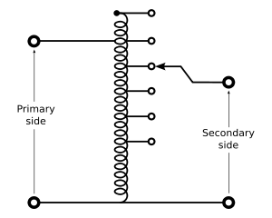
                    • For over 100 years the AUTO-TRANSFORMER has done the job well.

                      It started out not so efficient then improved. The E cores made of

                      iron were about 70 percent in Tesla's day. Today you can wind

                      a 14 awg wire around a circular shape core known as a "TOROIDAL CORE"

                      to achieve 95 percent. I do that no problem so you can too.

                      I spent a grand total of $40 bucks, delivered for my core.

                      A few feet of magnet wire and thus a few measly bucks worth

                      to form the well known AUTO-TRANSFORMER.

                      You can tap in every winding if you like and get a specific

                      voltage.


                      Once the DC voltage is established the ac voltages will fall

                      into line as well. Ac is easy. Tap into whatever location

                      you chose to get SOME voltage- Next- connect the well

                      known VARIAC or AUTO-TRANS and dial the desired voltage

                      in.


                      Now let's say you have a fluctuation and your voltage went up

                      50 volts. This can and has been controlled by switching relays

                      that sense voltage and move to the next tap on your AUTO-TRANS.


                      This is the way it has been done for a very long, long, long-long-long

                      time. No ardu's or atmega's, no fancy high end computers just plain

                      ole industrial level controls that the big business has depended on

                      for decades. The promise of cheap switchmode computerized

                      controls for large power levels are finally catching up these days

                      with an improved efficiency of 3 percent from 95-98 percent.


                      https://en.wikipedia.org/wiki/Autotransformer

                      Comment


                      • Full explanation including scope shots for the disgruntal

                        argumentative types who say Tesla mad a mistake with his

                        patent. 512,340


                        Note the carbon resistor, they don't lie when connected to a scope.

                        Now I know everyone is not going to hook up to a scope when

                        this has already been done for us over and over. A good meter can

                        measure frequencies high than 60hz and can accurately measure

                        voltages of all kinds. 1000 watts in and 2800 watts out with this

                        smaller bifilar coil. A larger coil could produce more on the output

                        for close to the same input plus 2 more larger coils could be placed

                        on top of one another for double this output.

                        Of course these coils that are bigger will produce very high

                        voltages with easy and need to be running at 500 volts to

                        keep the amps lower. Bifilar coils are high voltage units.

                        The energy is there but harder to convert down to power

                        household devices than it is to make the extra.


                        [VIDEO]https://www.youtube.com/watch?v=hI07DLlG3Qg[/VIDEO]

                        Comment


                        • Filtering

                          Thanks again Mike and Sprocket,I will get the stuff together that You spoke of Mike and build it,from there we can do proper measurements, and see what voltage I have,it will take a while as I work away from home and will only be there in two weeks time,but will keep you posted.Thanks for the drawing and advice

                          @Sprocket,I agree with you regarding the design of a circuit and that's exactly why I'm asking around,seeing that my knowledge is limited and formal training not to the standard of guys on this forum,nevertheless I am learning and willing to find a way to make it do what I planned,do you know of someone who can design the circuit you were talking about?

                          Comment


                          • Originally posted by BroMikey View Post
                            Full explanation including scope shots for the disgruntal

                            argumentative types who say Tesla mad a mistake with his

                            patent. 512,340


                            Note the carbon resistor, they don't lie when connected to a scope.

                            Now I know everyone is not going to hook up to a scope when

                            this has already been done for us over and over. A good meter can

                            measure frequencies high than 60hz and can accurately measure

                            voltages of all kinds. 1000 watts in and 2800 watts out with this

                            smaller bifilar coil. A larger coil could produce more on the output

                            for close to the same input plus 2 more larger coils could be placed

                            on top of one another for double this output.

                            Of course these coils that are bigger will produce very high

                            voltages with easy and need to be running at 500 volts to

                            keep the amps lower. Bifilar coils are high voltage units.

                            The energy is there but harder to convert down to power

                            household devices than it is to make the extra.


                            [VIDEO]https://www.youtube.com/watch?v=hI07DLlG3Qg[/VIDEO]
                            Thanks Mike,this answers a lot of questions,my measurements are way off if compared to what i saw here,and I think your Toroidal transformer is something to try out.The video made things a lot more clear for me and i saw the voltage if properly measured is closer to 220v than I thought,the signal however is way off if I look at the scopeand my theory about the sun is BS.But thanks again I will keep you posted on new findings
                            Regards
                            Paul

                            Comment


                            • No need to be so apologetic Paul

                              Hold your chin up because on this site you will get your

                              head bashed in by old men who never do any of the tests because

                              as they say it just won't work. You are miles a head of them.

                              Don't back up and keep fine tuning that machine because

                              you have more than a single bifilar Tesla coil there so

                              OVERUNITY is going to be higher. You don't need a scope

                              or a fancy meter. What did Tesla have? ZIP!!! That's right

                              Tesla had less than what we have and coils caps and resistors

                              will do just fine.


                              Keep your hands and chin up this is only round one.

                              Thanks for sharing your baby, the rest of the sheet picker

                              can take a hike all they do is complain, never point any direction

                              in their infinite wisdom. This shows malicious behavior.

                              I'll watch yer back.

                              Comment


                              • Originally posted by BroMikey View Post
                                No need to be so apologetic Paul

                                Hold your chin up because on this site you will get your

                                head bashed in by old men who never do any of the tests because

                                as they say it just won't work. You are miles a head of them.

                                Don't back up and keep fine tuning that machine because

                                you have more than a single bifilar Tesla coil there so

                                OVERUNITY is going to be higher. You don't need a scope

                                or a fancy meter. What did Tesla have? ZIP!!! That's right

                                Tesla had less than what we have and coils caps and resistors

                                will do just fine.


                                Keep your hands and chin up this is only round one.

                                Thanks for sharing your baby, the rest of the sheet picker

                                can take a hike all they do is complain, never point any direction

                                in their infinite wisdom. This shows malicious behavior.

                                I'll watch yer back.
                                Thanks Mike
                                I will do just that,at least something works for me so far,if I did not try I would not have known whether it will work or not."So far so good",My aim is to get off grid so this still have a long way to go before that will happen as time is precious and I don'have enough of it for all the things I must, and still want to do,but doers actually get some where, and don't worry I i'm not easily discouraged.

                                Comment

                                Working...
                                X