-
-
Double shorting video
Hey Patrick,
Just saw the double shorting video . Did not completely understand the significance . Could you explain a little more as to what is happening and how you plan to harvest the increase in voltage .
Shorting has become a new field of interest especially after Ismael Aviso's coil shorting energy videos ...
Will measure and put pictures regarding the 20 wire coil soon.
Thanks for your continued interest,
BhargavComment
-
-
This may help with reducing lenz's law and also increasing usable output. It's a two stage process and it makes sense when you consider that a low impedance such as an empty cap is better for capturing this high voltage spike.

Shorting coils circuits - AlternativeWorld EnergyComment
-
-
This is not my design, i got it from the link below the image but i did post stage one on here over a year ago before i knew about this. I thought this is what Bedini was doing in his 1984 free energy generator.
Maybe we could convert Bolt's circuit to use a couple of high power fets with low on resistance as i have read this will be closer to a mechanical switch than a bipolar transistor. We could also replace the trigger coil in the collection circuit to a hall switch and place it in line with the coil to remove the need for perfectly spaced magnets.Note the AC series cap in circuit - this will make it so the rotor will not slow or brake from lenz-law lugging during the filling of DC cap, and also during the discharge of DC cap to load.
A description of the purpose and function of this AC series cap is that it works like a "high bypass filter" - letting the high frequencies to pass right through, and charge cap, while blocking-out the lower end frequencies which will work to lug primary to higher amps draw.
Values of caps and ressitive load in this circuit are only examples of a particular model - experiments to find best AC cap, DC cap, load, rpms of rotor with mangets, coil size. pulse rates etc etc etc will be needed for particular applications and power outputs vs power inputs.Last edited by Zooty; 04-19-2011, 09:44 AM.Comment
-
I like the High power fet idea, any suggestions on which ones to start with?Originally posted by Zooty View Post
we've been using the MPSao6 to accomplish the "double short" it's beautifull we are working w/ small coils and the spike is only 400 volts, this is going to get crazy when scaled up.
I like hall's, we use them on the main SSG, control is much better than coil. for this method and w/ a single small coil we've been using an aircore coil to trigger, we've also had good charging and switching w/ a 3 rod core - stacked flat for less on time. frankly the magnets better be dead on anyway or these things do not charge as well IMHO, with such a small trigger, you can mount it right on/next to the main power coil. The circuit will work w/o the EB diode, however, the trigger coil likes to have it. you can do w/o the neon, however, w/o it, do not remove the charging battery unless you like to solder and have a few transistors at the ready.

PatrickComment
-
Hey Guys,
I've got my 3-pole kit set up as follows.
Running the motor on a single battery with the half bipolar switch directing the spike back to battery, its running on 12.23 volts, 35 ma @ around 2000rpm using 1 bifilar coil. Then I have my 2 single wire coils in series that I'm shorting out using a Bedini circuit and the other generator coil as the trigger. The spike which is run thru a FWBR to a 10uf250volt cap and back to the run battery. The cap only fills to 80-90 volts when disconnected from the battery at 1900rpm's.
In the first hour battery voltage has risen .01 of a volt. I let you know what happens after it runs a few more hours.Comment
-
Update:
I ran the motor for 12 hours and the small motorcycle battery I'm using for this test went from 12.23 down to 12.20. Not too bad for a 12 hour run. I will let the battery sit over night and see if it bounces back any then continue the test in the morning.Comment
-
Excelent!Originally posted by Mark View Post
we have had a good learning experience w/ that kit here are a few vids we posted that show a couple of Bedini/Cole experiments we did.
YouTube - Micro 3GT "Farris Wheel"
YouTube - John Bedini Ferris Wheel - Micro 3GT self start
YouTube - Micro 3GT Farris Wheel Cap Dump
PatrickComment
-
-
yes sir can you tell me connect the halls in the circuit?Originally posted by citfta View PostComment
-
hall effect
[QUOTE=ren;54687]Full circuit here
Half here http://rpmgt.org/mot.jpg
or here http://www.rexresearch.com/bedini/6392-2.gif
or here http://www.esmhome.org/library/bedin...schematics.jpg[/QUOTE
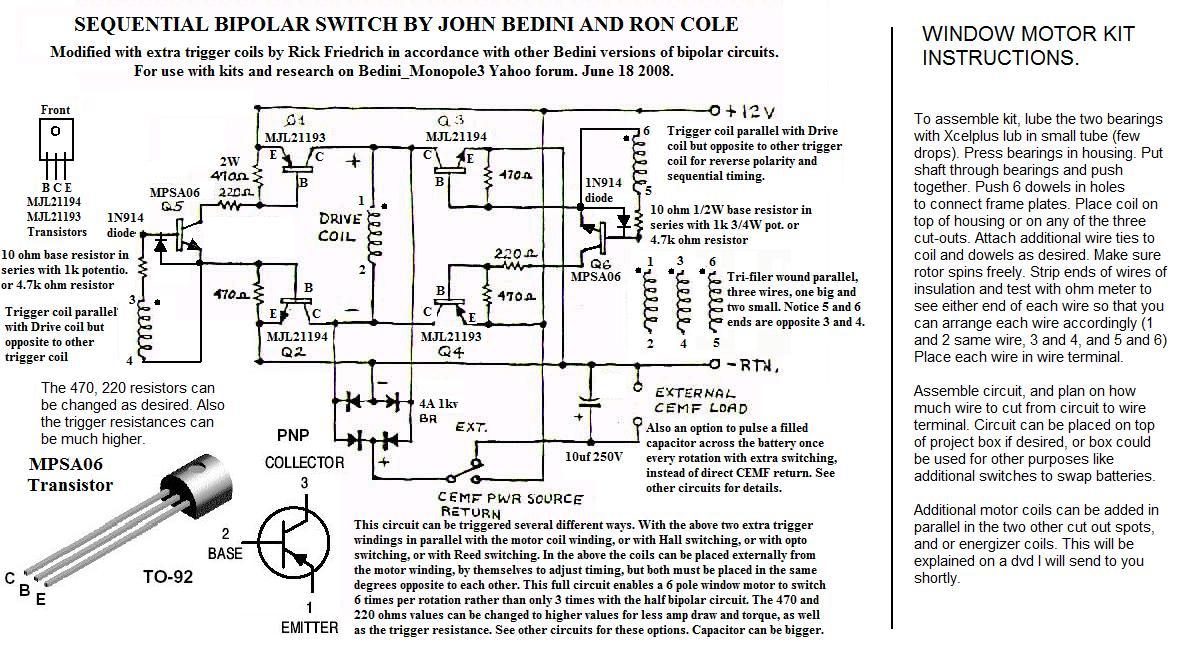
i have a window motor with 24 strands of wire and transistors and i want to use the hall effect to start the motor. i am using 10ohm base resistors . i am not familiar with the hall effect circuit for each strand i will have to use 2 transistors and 470ohm resistor. or i will only use one strand(wire) as drive coil and two transistors MJL21193 MJL21194.
ThnksComment
-
There needs to be no "www"here:Originally posted by MALEXIOU1 View Post
(At some point, the dons who run the Net should straighten out some of its strange anomalies)Comment

This forum is preserved as a permanent archive. The community continues at eMedia Press.
- If this is your first visit, be sure to check out the FAQ by clicking the link above. You may have to register before you can post: click the register link above to proceed. To start viewing messages, select the forum that you want to visit from the selection below.

 Tweet
Tweet

Comment