

 Tweet
Attached Files
-
-
Hi Gad. WELCOME to forum. I see this is your first post. I'll study this tonight and we'll make contact in the morning.
That's a lot of work you've done. Very nice.

Comment
-
Hi Gad,
Welcome to the forum !!
I looked at your posting and suggest that you insure that your using a schematic that has been proven with many hours of testing which is a modified version by Aaron of the Quantum article with some slightly changed component values by me.
Mosfet Heating Circuit
There are also a video library at Open Source Research and Development with numerous five (5) hour non stop video recordings of the circuit in operation.
I would recommend two video recordings showing the circuit running in the preferred mode of operation.
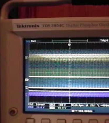
Tektronix TDS 3054C - January 9, 2010
Tektronix 2445A - January 24,2010
This should help you get going in the right direction
Regards,
Glen
 Open Source Experimentalist
Open Source Research and DevelopmentComment
-
thanks Glen, but i need a more detailed response in order to proceed, since i already watched some of the videos and it did not help me in this stage.
please refer to my questions if you can.
i'll consider changing the circuit after i'll get answers on my posted questions.
please understand that my current situation is that i read much of the info already published by Ainslie/Aaron/you/Panacea Bocaf/etc. and i need to bridge some gaps since i'm not an electrical enginner, so my questions are very accurate and needed a detailed answer.
I can consider building the whole circuit (with the 555) if i'm convinced it will help in this stage, which i'm not right now. at this point i'm trying to change the adjustable parameters (freq./duty cycle/R1) but not getting any self-oscillation (what waveform to expect exactly ? this is one of my questions here...)Comment
-
about your videos
also, from your videos it not clear when you get to the desired oscillation phase or not. i think you should log the video with some text annotations so it wil be more clear. for example - from which point/time you can start measuring the energy gain ?Comment
-
Hi Gad,Originally posted by gadh View Post
Well I'll try to answer some of your questions ...
1) Your scope is good enough to "see" 50% of the harmonics barely .... the January 24 - Tektronix 2445A is a 150Mz scope that is in one of the preferred mode of operation video compared to the January 9, 2010 - Tektronix TDS 3054C shows this without question.
2) You really cannot explain the wave form and it's changes in oscillation in conjunction with the 555 timer and not using a frequency generator watching the voltmeter voltage oscillating going up and down with the best example ever documented of the effect on January 9, 2010 a five hour video showing the battery voltage going up for about the first hour.
The required operation to get gains is not just in seeing the wave forms but from the 10K data dumps from twenty two tests both are really required for a proper evaluation of the results.
I would suggest you look at the 5 hour videos on the "Open Source Research and Development" site for your references and not the 10 minute YouTube videos, as Aaron did not get the results I did at all.
For all the testing and evaluation images and data for twenty two tests done which Test #13 was used in the "Open Source Evaluation of Power Transients Generated to Improve Performance Coefficient of Resistive Heating Systems" can be found here referenced at Energetic or use my Windows "LIVE" SkyDrive public site Mosfet Heater
3) Your method of measuring the temperature sounds good, I did what I could afford to get a base line to show results ....
4) I doubt the DMM could provide better information than the 10K and 100K data dumps from oscilloscopes that cost (TDS) $10,000.00 to (DPO) $15,000.00 dollars that was used in my testing ... but the DMM is very helpful in the tuning of the circuit.
5) [ in the current situation (as described in the images), can we expect gain of COP>1 ? ] ..... sorry, very doubtful
Hope this information helps.
Glen
Open Source Experimentalist
Open Source Research and DevelopmentComment
-
This is in the works .... especially the January 9, 2010 which starts from the 12 volt battery connection to the 555 timer first, showing the 22% service factor and connecting the 24 Volt battery bank and the 555 timer defaulting to a 50 to 55 % service factor .... and on to pot adjustments ....Originally posted by gadh View Post
Regards,
Glen
Open Source Experimentalist
Open Source Research and DevelopmentComment
-
sorry, i did not understand from the Jan 9 video. can you please attach a few screenshots from it and explain which of them are in tuning period only and which are in the desired state ?
also, my scope is supposedly better than the 2445A, so isn't it enough for this experiment ?Comment
-
SURE, no problem .... time for me to go to work, so it will be latter to day or tomorrow.Originally posted by gadh View Post
Yes your scope is good enough for research I found the harmonics with mine ... took me awhile though not knowing really "what" to look for 
Glen
Open Source Experimentalist
Open Source Research and DevelopmentComment
-
some other questions :
1. if i use the same circuit as Ainslie, with the only diff. is the Ohmite as the load resistor , and i get to the desired self-oscillation mode - what COP should i expect ?
2. how much COP did you get in your modified circuit ? i did not see any COP data in your tests/docs.
3. how much COP did Aaron get in his circuit ?Comment
-
Comment
-
thanks pal for your support !
I indeed am going to build the 555 part since i think it plays a big part in the expected oscillation.
As for the load resistor of yours - check your inductance first. we've measured ours using a capacitor connected with parallel to the resistor and passing AC thru it with a certain freq. since we did not have an accurate inductance meter in the micro-henries range (hard to get, costs at least 200$ i think).
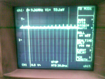
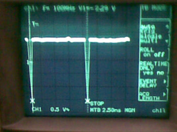
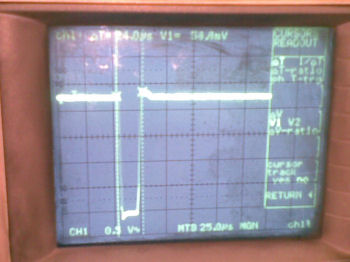
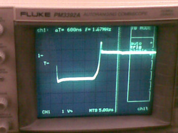
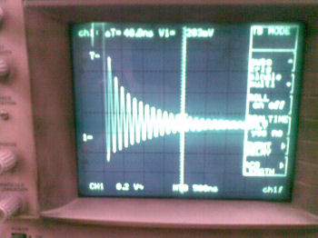
As for the waveforms, i think we should expect some sine waves coming on top of the regular waves generated by the 555 (2.4khz). see my attached images taken from Glen's video's.
I think all the "harmonics" and "sub-harmonics" for a "no-pro" like me means that we expect to see waveforms that look like an audio waves...
Glen - am i in the right direction ?Attached FilesComment
-
-
@Gadh
Hi Gadh,
I read your email. Thanks for bringing the discussion to this thread.
I personally don't have time to get involved with this thread at this time
and with Rosemary, Glen, Harvey, etc..., they're able to answer any
questions you may have and they are active in with these circuits now.
There is also the other subforum for Glen's group.
The only heat gain that I saw on my tests were some battery draw down
comparison where the Quantum circuit and variation of always gave me
a longer running time. I never posted the results of any of these tests.
I did have over 100C above ambient at a 60% duty cycle with the original
as published circuit in the Quantum magazine and the battery didn't drop
1/100th of a volt over 30 minutes to an hour. I will revisit that exact setup
at a later time.
Good luck with your project - you're in good hands here!Sincerely,
Aaron Murakami
Books, Videos, ESTC Conference Info, Blog, etc. https://emediapress.com
Comment
-
Thanks Aaron for your blessings.
BTW, about the common claim here about the fact the battery voltage did not drop in a long time - just know this is no indication at all for the energy drawn from it. I talked to one of the best lead-acid battery experts in my country (who had also issued some patents in this field), and he told me that this is a common behavior for this type of batteries - the voltage can start dropping only when the battery is almost completely drained and not before that (in some cases).
I was also hoping that you will test the COP - since its the most important fact we need to approve here (some will say - the only fact !)
also guys - why none of you had thought to test the heat dissipation with a calorimeter or a hand-maid one like i suggested ? it seems the most accurate way to measure as i stated before.Comment
-
Hi Gad,
This is true. As a result we NEVER took battery draw down rates into the argument. But what is definitely atypical is that the battery actually shows a 'recharge' under 'load' conditions. And this is certainly not in line with classical prediction. And that 'recharge' is consistent with the measured rate of discharge across the shunt resistor.Originally posted by gadh View Post
More to the point is this. 10 years ago, I was roundly advised by mainstream that it is IMPOSSIBLE to return any energy to the battery. This general opinion now appears to be revised.
Where Aaron's tests deviated was that he was consistently able to return more energy to the battery than was delivered. But this at very low wattage.Originally posted by gadh View Post
Gad. When the measurement of heat indicates a wattage of - for example - 10 watts - and the energy delivered by the supply source is - for example - 1 watt - then that's an evident gain of x 10 over the supply. If one allows for errors in calorimetric values of - say - 5% which is reasonable - or 10% which is stretching it - then add 5% or 10% or even 50% to the amount of energy delivered and you still have an indisputable gain of energy dissipated against the energy supplied. If the numbers were too small - or the difference barely noticeable - then indeed one would need really accurate measurements to determine the COP values. But as the range is extreme - that level of accuracy is simply not required - not even by those many professors who have seen this claim.Originally posted by gadh View Post
Check your pm's. I'll try and reach you there.
Comment
Comment