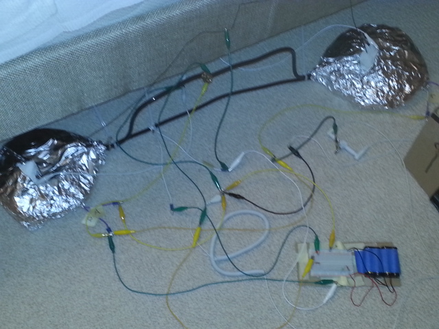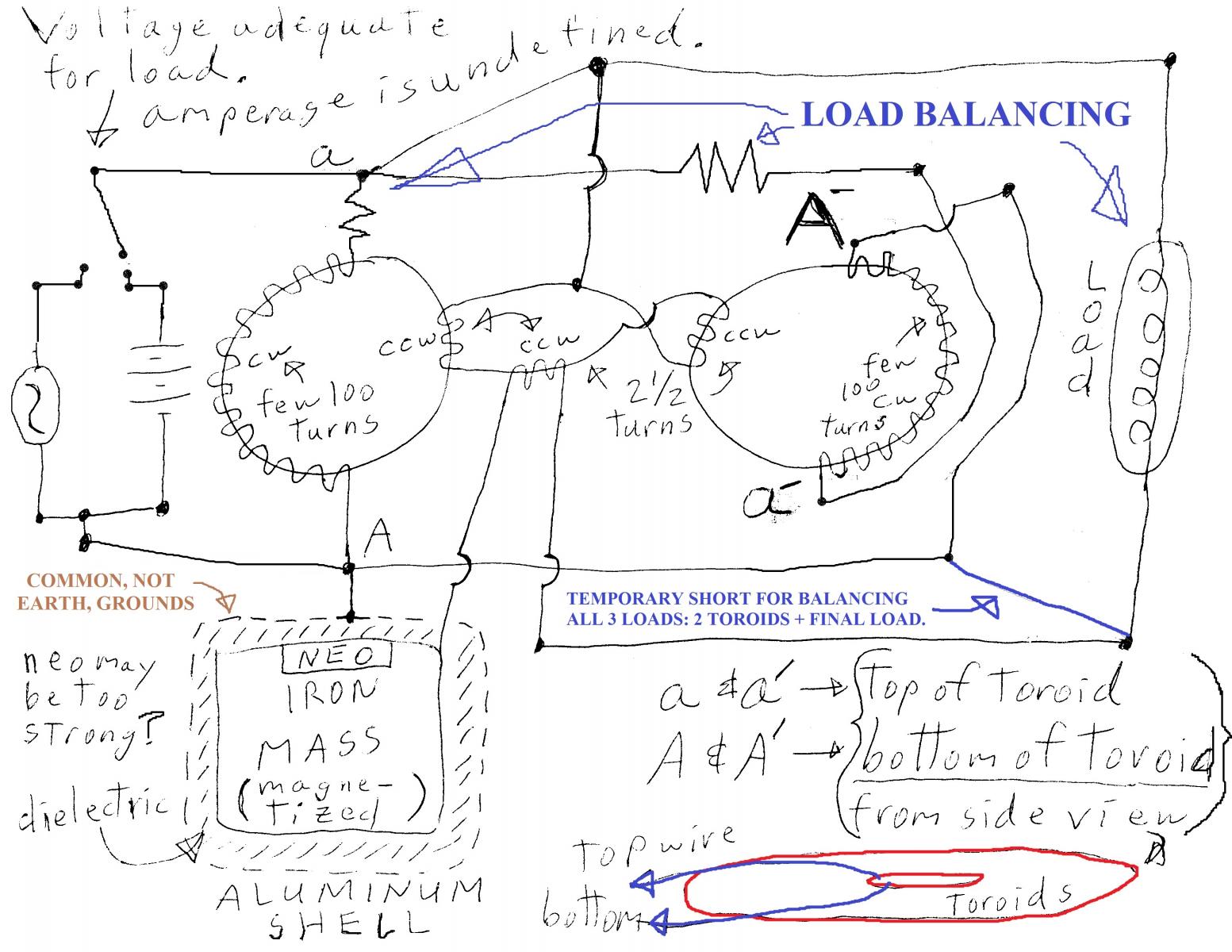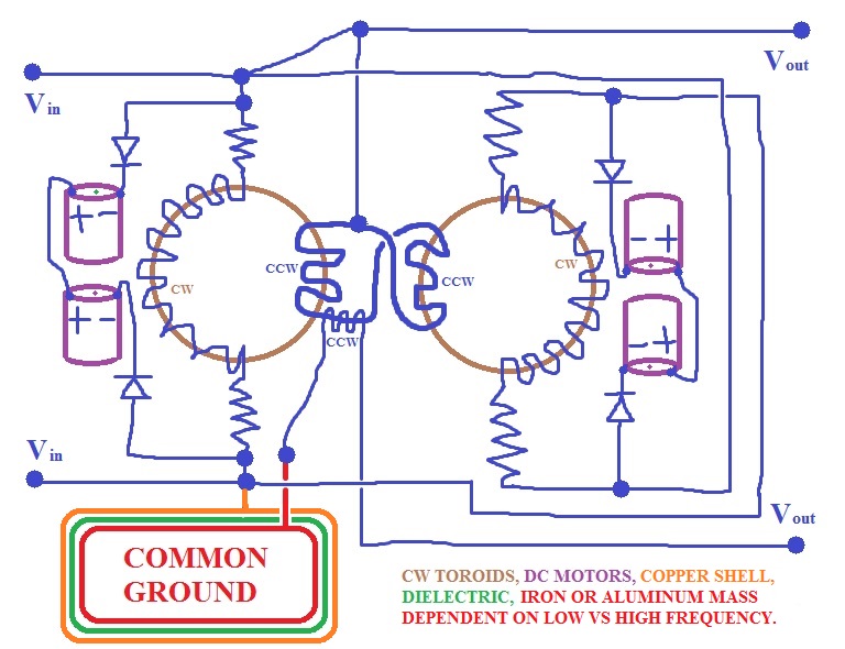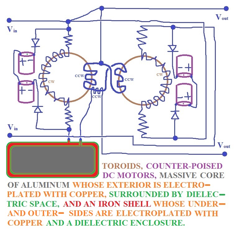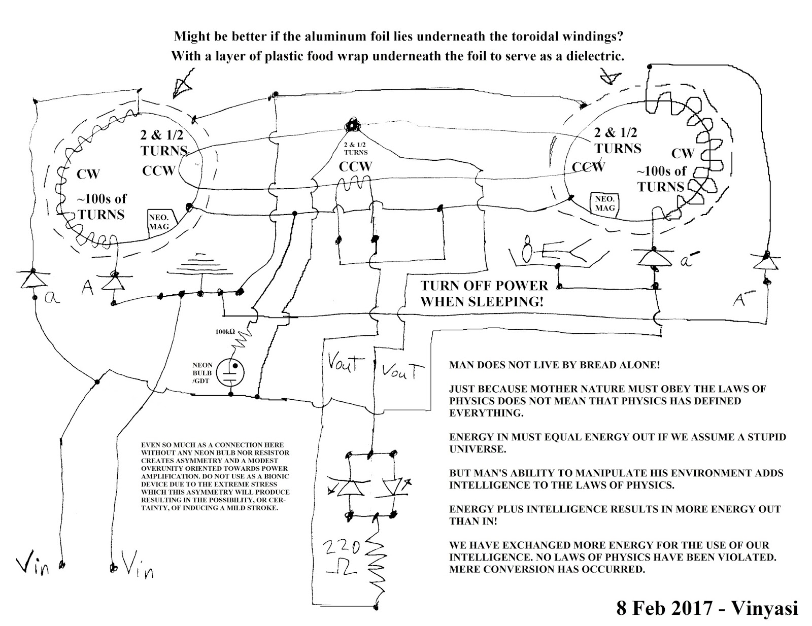
Since I have a penchant for believing that B&L is a reincarnation of Tesla's Special Generator, and since we know so little about William Lyne's description of the latter to replicate it, and since my own experiments at EarthingLife.info to discover what the latter actually is has spawned a new breed of B&L devoted to the welfare of the body as a bionic sleep circuit in the course of attempting to also make it work as a power magnifier for machines, I'm starting this new thread apart from my two prior haunts at Barbosa and Leal Devices - Info and Replication Details and Tesla's Special Tri-Metal Generator with a video, three rough sketches and a photo of a first attempt at a modified emulation of Clarence's replication of B&L based on my analysis at the three links above plus my B&L and TSG blogs.
Announcement
Collapse
No announcement yet.
Barbosa and Leal Developed as a Bionic Device
Collapse
X
-
Common ground, construction material dependent on frequency?
Whether the mass for increasing output is iron or aluminum may depend upon the frequency applied to it: high for aluminum vs low for iron, or maybe incorporating both by favoring high over low?Last edited by Vinyasi; 02-05-2017, 03:33 AM.
-
Solid State vs Kinetic
Maybe it's possible to neutralize the Lenz effect with something other than two primaries wound on a pair of stationary, counterpoised toroids?
Maybe a pair of counterpoised, brush DC motors can also do the job?
Although, if the Lenz effect is truly balanced with counterpoised DC motors, then maybe they won't move? If either one does manage to rotate - if even slightly, then maybe a resistor or small coil has to be placed somewhere adjacent to one of its leads to slow it down or stop its rotation? Making this a substitute for toroids, not an alternative for solid state primaries within B&L's circuitry?Last edited by Vinyasi; 02-18-2017, 07:45 AM.
Comment
-
Symmetry & Sleep vs Asymmetry & Overunity
I don't possess fancy shop equipment nor the skill to use them. All I ever use are a basic meter to test for continuity (have I connected two wires together, or am I kidding myself?), and simple inferences such as: the use of LEDs to test for the presence of amperage flowing in any position of the circuit relative to any other position with a similar LED placed there and which way does it flow? But my most important piece of equipment is the sensitivity of my own body, coupled with my intuition and limited expertise for interpreting results and what to do next. For this latter factor I owe my debt to the fortuitous discovery of other peoples' thoughts and experiences (here at Energetic Forum) on specific instances which are relevant to my study.
After testing out the circuit, above, and its overunity analog with neon bulb / resistor or resistor alone, below ...
... I've come to the conclusion that the 'idle mode' for this device is unity or less than unity, but not overunity due to its symmetry and lack of overunity whenever its neon bulb is missing ....
This latter condition is ideal for sleeping wherein the body wants to achieve balance during its period of rest. Overunity is a condition of asymmetry ideal for achieving Coefficients of Performance greater than one, but lousy for achieving deep rest, or any rest. Instead and more than likely, a condition ripe for cancer or a stroke will be the result of sleeping in a condition of asymmetry.
Last edited by Vinyasi; 02-10-2017, 04:10 AM.
Comment
-
Replacing Grounding Rods and Neon Bulb with a Four Plate Capacitor
I'm guessing that the main driving force behind B&L is the electrostatic field which it creates among the various grounding rods. Strong geomagnetism may indicate a parallel symptom of strong geoelectrostatics as well. Both will contribute to raising or maintaining the voltage delivered to the Captor Loop. The shape and orientation of the grounding rods is not unlike that of an emitter of an ion generator: a needle tip. So, an interactive relationship with the Earth is not unlikely. And the preferred embodiment of each grounding rod, copper plated steel, certainly lends the notion that geomagnetics is not a trivial influence.
With all of this in mind, it is not hard to imagine possible alternatives to an Earth-based B&L.
Comment
-
Electrostatic Reception of Natural and Manmade Power from the Earth
Electrostatic Reception of Natural and Manmade Power from the Earth - a YouTube video
Comment
-
Separating our Symmetrical Devices from our Asymmetrical Devices
Separating our Symmetrical Devices from our Asymmetrical Devices - a YouTube video
Comment
-
What Do We Know About Geology To Help Explain Barbosa and Leal's Use of Ground Rods?
Resistivitynear the surface of the Earth, it can be inferred from this that Barbosa and Leal does not seek to magnify capacitance in their circuit as a singular factor. In other words, the Earth doesn't represent a huge capacitor to the energy traveling around inside of B&L's circuit. The Earth is more likely a weak resistor. But this allows for this circuit's characteristic emphasis to lie elsewhere among some other factor of electrodynamics. This terrestrial resistance acts as a weak load which is ever present. Such mild loads are usually held as safety checks to disallow the circuit from frying itself should no load be engaged when the circuit is first turned ON.
Electrostatic Depth
The ground rods are kept closely spaced. One meter separates their radius. This implies that only the length of each ground rod is the depth of DC Electrostatic ResistivityElectromagnetic Depth
On the other hand, the depth to which any electromagnetic wave (emanating from out of B&L's ground rods) can penetrate the Earth is determined by a lack of Resistivitydepth penetration increases with a decrease in frequencyMy AIMS Essay.
Induced Polarization
current can be induced on another wire as a result of the shorter distance of separation between the two wires [proximity of grounding rods]
Induced polarization may be time-domain, where controlled current signals are introduced into the ground through the two current electrodes, and the overvoltage between the signals is measured across the two potential electrodes. It could also be frequency domain, where the alternating current fed into the ground depends on frequency. It makes use of the principle that, when an alternating current is passed into the ground, the apparent resistivity of rocks in which polarisation can be induced is higher with low-frequency current than with higher-frequency current. This is because the capacitance of the ground inhibits the passage of direct currents but transmits alternating currents with increasing efficiency as the frequency risesMy AIMS Essay.
3.8 Pulse-transient electromagnetic systems
My AIMS Essay.
Field AntennaOrientation of Ground RodsGalvanic Response
It can't be ignored that the copper plating on each ground rod, overlaying its inner steel, creates a mild battery of electric charge despite the seeming mildness of this contribution towards the overall charge imparted to the soil by B&L's circuit.
Terrestrial ResponseLast edited by Vinyasi; 02-25-2017, 02:27 PM.
Comment
-
Simulating Barbosa and Leal, version 4
And here's the exact same configuration except that Eric Dollard's analog computer in Longitudinal Magneto-Dielectric mode (not optimized for resonance) is substituting for the two ground rods in the example, above:
Notice anything peculiar when comparing the output of these two simulations?
The ground rod version manages to put out what appears to be a slight overunity by virtue of the wattage and amperage of the power sources sometimes going negative indicating a feedback of sorts undermining their expense of energy?
The light bulb's voltage is steady at 120 volts.
But its temperature, as measured by the simulator in Kelvins
Comment
-
Lengthening Oscilloscope Flash of Neon Bulb's Spark Gap with Help from a Capacitor
I don't know about you, but I don't like messy appearances (have I looked at myself in the mirror, lately?).👻
If an unregulated neon bulb / spark gap fires rapidly many times during each half-phase of an AC cycle creating peaks and troughs (of each spike) which are shallow by comparison to withholding the arcing to accentuate the height or depth of each spike, then maybe this is better? I don't know...
I found that by placing a capacitor across the neon bulb (in parallel with it), I could get the desired result by examining this simple example of a flashing neon bulb...
Here's another one...
Reference: [SOLVED] Neon Flasher Simulation at EdaBoard.com
Compare those clearly defined arcs to these messy ones...
Displaying a Rapidly Firing Neon Bulb of B&L with Two Grounding Rods

Displaying a Rapidly Firing Neon Bulb of B&L with Eric Dollard's LMD

Now, here, I've cleaned them up...
Last edited by Vinyasi; 02-25-2017, 10:59 PM.
Comment
-
Reducing the AC Sources to One
Comment
-
This simulation uses Iain Sharp's JavaScript port of Paul Falstad's Circuit Simulator originally written in Java. I've converted B&L's Electric Keeper (in the center of their circuit)...
... into one LMD module of Eric Dollard's Analog Computer in Longitudinal Magneto-Dielectric mode normally useful for bench testing emulations of various types of AC transmission lines. No animals were harmed in the making of this simulation.
Go to this link to download a blank simulator canvass into your browser's window:
https://is.gd/blankcanvass
Download this file and then load it into your browser's blank simulator:
https://is.gd/BL_LMD_v1d
Then...
ROLL YOUR MOUSE WHEEL DOWNWARDS FOUR NOTCHES TO EXPAND YOUR VIEW OF THIS CIRCUIT AND (HOPEFULLY) CENTER THE SCOPE LABELS.
The shortcut for this blog is:
https://is.gd/eureka_v1
Here is the backdrop to how I managed to evolve my thinking to achieve this with a two hour video composed of my prior development. Enjoy!
[VIDEO]https://www.youtube.com/watch?v=yvI4dQ87Vws[/VIDEO]Last edited by Vinyasi; 02-28-2017, 05:20 PM.
Comment
-
Reality of Negative Resistance is Free Energy and Overunity. Wikipedia implies this.
A gas discharge tube is a negative resistor. Find them in every neon bulb and every fluorescent tube (without its ballast).
Don't allow Wikipedia to tie us up in knots of confusion involving circular reasoning to obfuscate the truth of negative resistance. Ignore Wikipedia's confusing analogy that amperage drops as a consequence of voltage, and confusingly vice versa. Focus, instead, on the truth of negative resistance neatly tucked away in a simple math relation: the speed of amperage increases as the friction of resistance increases. And since the speed of amperage times the pressure of voltage equals the power of watts, then an increase in friction results in an increase of power. Overunity and free energy is this simple!
My simulation of negative resistance...
[VIDEO]https://www.youtube.com/watch?v=-0mio2PRd2M[/VIDEO]Last edited by Vinyasi; 02-28-2017, 09:09 AM.
Comment
-
Oscillating Power is a Hysteresis of Duty Cycle imparting an Illusion of Free Energy
I don't think that my little simulation of Eric Dollard's LMD (analog computer in Longitudinal Magneto-Dielectric mode) actually produces power inside the LMD module when the AC power source is shut OFF. Actually, I think that each cycle of oscillation begins before the last one ends building upon the prior and gaining a little more amplitude with each successive cycle giving the appearance of energy from the vacuum - energy created from nowhere. But it sure does look - for all intents and purposes - as if that is what has occurred whenever certain switches are engaged and others are not. I don't remember which ones. You'll have to play around with it...
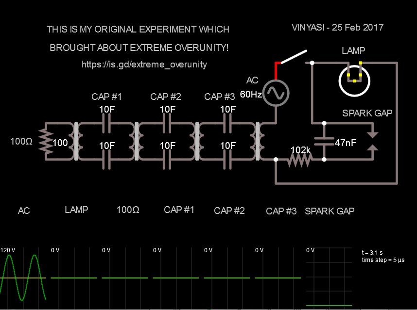
I hope to do a chart of all eight possible combinations of switchings and their outcomes. In the meantime, I'd like to share with you what I went through the very first time I simulated free energy in disastrously humongous proportions...
In both of these two varieties of Extreme Overunity, a strange anomaly occurs. You think you're being dandy by shutting OFF the AC power to prevent any further mischief, but what happens? The amps, volts, and watts skyrocket even faster than when the AC power had been ON! No fooling!
And where does this escalation occur? EVERYWHERE in the circuit!!!! Now, that's indiscreet OVERUNITY!
Here is a very simple version of this basic concept with only four switches and a modest, rock solid output hanging around the kilo-volt range. Two additional loads are added to the inside of the LMD module...
And here is a very long video describing my inspired thinking on why some of us are convinced that free energy arises from out of nowhere – whenever it occurs as the result of oscillating power, but actually comes from hysteresis originating in the NEGATIVE RESISTANCE of a GAS DISCHARGE TUBE, or SPARK GAP, and then spreads throughout the circuit infecting everything including the load due to HYSTERESIS becoming applied to all of the components of the circuit (including the load - which is attached and must be included). This pervasive hysteresis is the byproduct of severe stress shocking the whole circuit to sustain the belief among all of the circuit's various components that they, too, are NEGATIVE RESISTORS just like the spark gap.
[VIDEO]https://www.youtube.com/watch?v=L8klrsqHCOM[/VIDEO]Last edited by Vinyasi; 03-02-2017, 09:53 AM.
Comment


Comment