
This forum is preserved as a permanent archive. The community continues at eMedia Press.

Announcement

Collapse
No announcement yet.

Quadfilar, two Hi Voltage bifilar's in series (Cook Battery?)

Collapse
X
 
  • Filter
  • Time
  • Show
Clear All
new posts

  • #16
    Twin parallel coils in series.

    I wired the quadfilar coil once so that the beginnings and ends of the eight wires formed 4 closed loop coil. I connected the four closed coils to the four coil connections on the Bedini SG circuit, and ran a spinner up the same as if it were series hi-voltage. I have no explanation of how that coil worked the way it was wired.

    The Cook battery will work wired the other way too, and I think I was useing that wrap in the video. That one goes from top to bottem instead of straight accross. The bottem of number one goes to the top of three. The bottem of two goes to the top of four. The top of two goes to the bottem of three, and the capacitor is wired to the top of number one and bottem of four. Either way, all the wires are connected to one another and the to the capacitor.
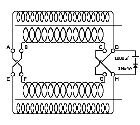
    Last edited by Allen Burgess; 07-24-2012, 08:47 PM.

    Comment


    • #17
      not Zerofossil fuel

      Originally posted by Allen Burgess View Post
      Interogatory from Zerofossil fuel:

      So you have two bifiler coils in series that would just be a quadfiler unless you have some type of center tap. am I understanding right you are saying this is pumping power into a cap if that is the case that is awesome. there are no other parts involved but a coil and cap? Also just to let you know you got a strong neodymium magnet setting on your laptop that is not a good idea, just fair Waring it can damage you hard drive,

      Reply:

      You have to start it up. I shake a tube magnet up and down inside the coil core untill a strong enough charge builds in the capacitor to sustain the oscillation with the coils.
      this was not Zerofossil fuel it was ZeroPointFuel
      Tecknomancer
      Zeropointfuel.com

      Comment


      • #18
        Allen, Thank you for all your experimenting. I am trying to replicate your "intercom coil" but even with all you have said, am not POSITIVE of the wiring, with the diode and capacitor included. A picture is worth a thousand words. Could you PLEASE post a CIRCUIT DRAWING. I have the exact white/black/orange/green spool of intercom wire in your video, but can not make out the connections. And words are so ambiguous. Please help those of us trying to replicate your experiment by giving us a drawing. Thank you very much for your work, and any further help you will give.

        Comment


        • #19
          Cook wire JPG

          @dibeeson,

          Take a look at this "Cook Battery" schematic:

          There are four coils; Two pairs of parallel coils. So you need to begin by striping the inside leads. Then you should connect the top coil in parallel to the 3rd, and the 2nd to the 4th. Then you attach the capacitor electrodes to the ends of the two looped coils, in series with a fast switching diode. Polarity is important, so try and determine that first by testing with a multi meter! You need to place a strong sphere or diametric Neo in the coil core to start the oscillations. It should work like a shake magnet flash light for testing, then it should continue to oscillate and continue to generate power on it's own. This circuit is identical to the "Danial McFarland Cook" Electro-Magnetic battery. Two LL parallel tank coils in series.

          Daniel McFarland Cook's Electro-Magnetic Battery
          Last edited by Allen Burgess; 07-20-2017, 02:16 PM.

          Comment


          • #20
            Like this?

            @ Allen.
            Like this?
            Attached Files

            Comment


            • #21
              Wire diagram.

              @Dibeeson,

              That's perfect. Place a neo sphere magnet inside the coil core, then attach your multi-meter electrodes to those two junctions and test for polarity first. One side should show a negative sign on the voltage reader. Then select the proper side to wire the diode to correctly. You should start reading a charge immediately in the capacitor!
              Last edited by Allen Burgess; 02-01-2014, 10:15 PM.

              Comment


              • #22
                wire diagram.

                @dibeeson,

                Try connecting the capacitor and diode in series between the junction from the inside loop to the junction of the other outside loop.

                Comment


                • #23
                  Coil-cap-diode clarification

                  Hi Allen
                  Following with interest here and on OU. I went to Home Depot and bought some short lengths of iron pipe (1/4" and 1") to try a Cook battery as per your specs. You're saying the end of the inner tube should connect to a cap, then diode, then the outer tube (based on polarity) on both sides?
                  Bob

                  Comment


                  • #24
                    Cook battery.

                    @Bob Smith,

                    Where did you get the design plan for the iron pipes from? The design I used involved plastic dielectric conduit to house the ferrite or magnet core, and two gauges of wire wrapped around that, with electrical tape in between.

                    I just concluded a test between a serial bifilar coil and single wire coil of the same length and gauge wire. I wrapped a bifilar and single layer coil on a hi-permeabilty ferrite core, "Lasersaber's" joule ringer type.

                    I jolted both coils. Each coil showed 5 Ohms of resistance starting out. The SBC began to ring, and over night built to 25 Ohms, while the single wire Ohms stayed the same. Resonance is equal to a resistor of infinite resistance, so the increase in Ohms indicated a rise in resonance.

                    Tesla patented his bifilar Pancake as a "Coil for Electromagnets". I charged a bifilar wrapped nail left overnight, and in the morning it had imparted a permanent magnetic strength to the iron core.

                    This is the kind of oscillation that takes place in the Cook battery. What do you have planned for a core material?

                    Comment


                    • #25
                      Originally posted by Allen Burgess View Post
                      @Bob Smith,

                      Where did you get the design plan for the iron pipes from? The design I used involved plastic dielectric conduit to house the ferrite or magnet core, and two gauges of wire wrapped around that, with electrical tape in between.

                      I just concluded a test between a serial bifilar coil and single wire coil of the same length and gauge wire. I wrapped a bifilar and single layer coil on a hi-permeabilty ferrite core, "Lasersaber's" joule ringer type.

                      I jolted both coils. Each coil showed 5 Ohms of resistance starting out. The SBC began to ring, and over night built to 25 Ohms, while the single wire Ohms stayed the same. Resonance is equal to a resistor of infinite resistance, so the increase in Ohms indicated a rise in resonance.

                      Tesla patented his bifilar Pancake as a "Coil for Electromagnets". I charged a bifilar wrapped nail left overnight, and in the morning it had imparted a permanent magnetic strength to the iron core.

                      This is the kind of oscillation that takes place in the Cook battery. What do you have planned for a core material?
                      Allen, to be truthful, I thought the Cook "battery' was simply one iron rod with a coil around it, slid inside an iron pipe with a coil around it as well. Your quadfilar coil (I watched the video a couple of times) seems to perform as the cook battery would be expected to, in my mind. I thought to simply use the iron pipes, one inside the other, with the coil-cap-diode-to-coil arrangement at each end, inner to outer. My assumption was that in this way, the arrangement of coils would perform similar to the Tesla swbf coil, though in a slightly different configuration.
                      I've started winding the inner pipe with single stranded telephone wire, and the outer will be with multi stranded 20 gauge. I was going to go by your coil-cap-diode-coil arrangement, and connect them in series, as per the Cook patent arrangement you've described above.
                      Bob

                      PS I was planning to use electrolytic caps. Would you concur with this, or use some other type?

                      Comment


                      • #26
                        @Bob Smith,

                        You'll need a dielectric layer between the iron pipe core and the wire to build capacitance. You shouldn't wrap the wire directly over the Iron. A few layers of plastic dielectric tape should be added at the very minimum.

                        "ELECTROLYTIC CAPACITORS" are the best!
                        Last edited by Allen Burgess; 02-09-2014, 03:10 AM.

                        Comment


                        • #27
                          Thanks Allen
                          I'll have to do some unwinding and tape the pipes. I should have enough caps for this. Hopefully by the end of the day.
                          Have a good one.
                          Bob

                          Comment


                          • #28
                            Is Cook patent an LC tank circuit?

                            As a follow-up to Post No. 26 regarding the need for capacitance, notice how the description given by Cook is that of someone who has spent many hours on the workbench. He talks of electrical resistance, but the notions of inductance and capacitance are absent from the discussion (although the term induction is used in the title). As to be expected, given the Cook patent (No. 119,825) was issued October 10, 1871 while the Tesla patent for an electrical condenser (No. 464,667) wasn't issued until some 20 years later (December 8, 1891).

                            If we read carefully, we find the makings of a paired set of L-C tank circuits: Version No. 1, (Figure 1) Cook describes the primary helix wire as 30 gauge of less, and the secondary as 16 gauge or higher, all wire well insulated. Version No. 2: The primary helix is made of uninsulated wire insulated only between the coils (meaning each layer). In this version, the primary would have higher capacitance, than an insulated wire primary version. Version No. 3: Spiral ribbon used for the secondary coil, which would raise the capacitance of the secondary.

                            From a historical perceptive, Faraday and Henry each discovered, independently, induction in 1831. Henry, in 1845, demonstrated electrical current could be introduced from one coil to another. It is my belief Cook's "Improvement in Induction-Coils" patent was the next logic step in the development of electrical circuit design theory, but little did he know he actually discovered the L-C tank circuit.

                            Comment


                            • #29
                              Got my iron pipes wrapped as per Allen's direction, and wrapped in wire. I put them together as per the Cook patent (basically 2 swbifi coils in series), and quickly put a cap between the individual coils of each bifilar (no time for soldering in and adding diodes). I had some interesting ringing down of voltage after passing a neo over the outer coils, and what seemed to be some climbing of voltage as well. Still, I have to get my caps aligned with the proper ends of the coils, and diodes will follow from there- might take a few days to get the time.
                              Interesting info, Morningstar.
                              Bob

                              Comment


                              • #30
                                I got my windings all together and put the caps between windings as per your directions, Allen, for the Cook patent specs. I tried Mylar caps and electrolytic caps, with hi speed switching diodes. I was able to get some ringing down and bounce back of voltage, with some initial climbing, but not enough to self-sustain.

                                Allen, I still believe your coil-cap-diode arrangement with swbf coils in series is the way to go. I guess I need to do the config on a single core (better to first replicate what's demonstrated, then try something else), I'll try to get at it in the next couple of weeks - my time is pretty limited right now at home and on the road.
                                Bob

                                Comment

                                Working...
                                X